Backwash Supply Pumps Manufacturer O&M (PDF)
Filter Area Sump Pump Systems Manufacturer O&M (PDF)
Filter UD Media Wash Troughs Manufacture O&M (PDF)
Description
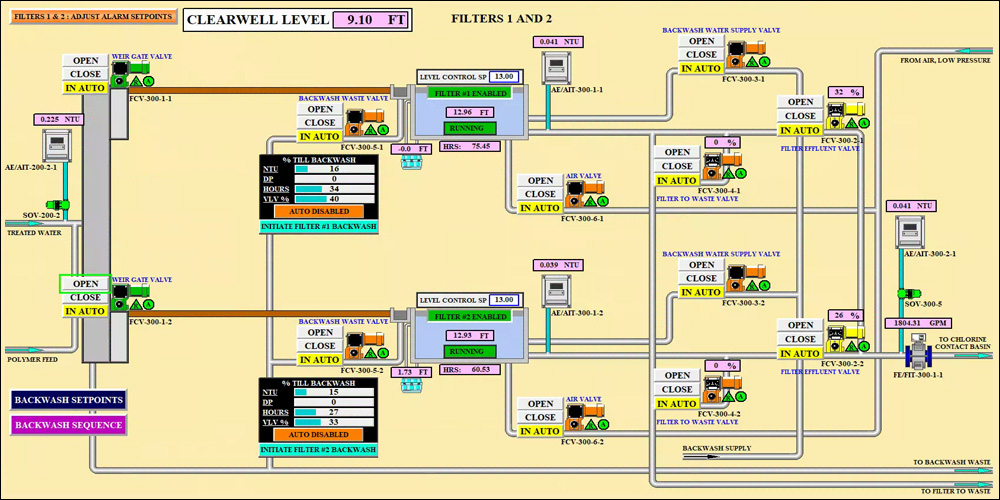
The TW from the Contact Adsorption Clarifier units flows into the common filter inlet channel. Filter aid can be added to the flow stream. Four (4) filters are available for treatment and are on-line or off-line based on the inlet weir gate position. TW flows from the channel over the weir control gate for each filter and into the BWW gullet, then into the filter through the BWW wash troughs. Water is filtered down through the filter media, into the filter underdrain, and then routed through the filter flume into the FE piping. A flow control valve modulates to maintain water level in the filter, and the FE pipe is manifolded into the combined FE piping and routed to the contact basin.
Filters are backwashed automatically based on several parameters, or backwash can be initiated manually. Upon backwash, the inlet weir gate slowly closes, and the FE valve remains open, draining the filter water level down to the top of the BWW wash troughs. The FTW valve will then open as the FE valve closes and continue to lower water level down to approximately 6 to 12-inches above the media level. The FTW valve then closes, and the air and water backwash sequence begins. After backwash, BWS water is used to fill the filter to the operating water level and then closes. The inlet weir gate opens allowing TW into the filter and the FTW valve opens, modulating to maintain the water level. The FTW process proceeds, until the filter is ready to be put back on-line, indicated by reaching an operator set turbidity value and maintaining that value for an operator adjustable time. The FTW valve then closes, and the FE valve opens, beginning the filtration cycle.
Individual filters may be taken OUT OF SERVICE or placed IN SERVICE at the PCS by using a single push button. Taking a filter OUT OF SERVICE shall shut down all of the associated equipment and instrumentation, close all associated flow control valves, as well as disable all alarms from the selected filter. Conversely, if a filter is placed IN SERVICE, all of the equipment, instrumentation, flow control valves and alarms are enabled for operation.
Each filter is manually placed in service from the PCS as described above. There are five (5) valves and one (1) inlet weir gate for each filter to control operations. At the beginning of a filter cycle with a “clean” filter, the FE flow control valve is slightly open (~5-10%) to maintain the operating water level in the filter. As the filter media clogs with solids, the headloss builds across the media and the FE flow control valve slowly opens, transferring headloss from the valve to the media. The headloss across the filter media, IFE turbidity, filter run time, and FE FCV position are continuously recorded on the PCS. Eventually, the filter effluent valve is opened to a maximum value, 80 percent of the fully open position based on the flow characteristics of the supplied valves. Upon reaching this valve position, further opening of the valve cannot effectively control the water level. An operating filter is automatically placed into backwash mode by any of the following conditions, which are all operator adjustable:
- High turbidity value (NTU)
- Maximum filter run time value (hours)
- Maximum FE FCV open position (%)
- Maximum filter media headloss value (feet)
Each filter has a FE sample station used for turbidity compliance and overall filter operation. The sample tap is just downstream of the filter outlet and captures the turbidity whether the filter is in FE or FTW mode. Each sample station consists of a sample pump that routes water to the FE turbidimeter. The filtration control panel LCP-300 utilizes the FE turbidity values to determine when a filter requires backwash, and when a filter can be placed back into service after FTW mode.
After backwashing, the filters are turned back on-line, but FE is diverted to the backwash waste pump station for a set period of time to accomplish FTW. This is recommended due to the initial spike in turbidity that is common to granular media filters. This “ripening” effect should typically last only a short period of time, usually less than 30 minutes at higher loading rates If filters are operated at lower loading rates (based on filters on-line and flow rate), the FTW period may take longer. After a backwash, the filter is “full” of clean backwash water, around 13,000 gallons. As RW is introduced into the filter during FTW, this water must displace the backwash water. At the full loading rate of 700 gpm (4 gpm/sf), it takes 18 minutes to displace the volume. At half the loading rate of 350 gpm (2 gpm/sf), it takes 36 minutes to displace the volume. The ripening of the filter and lowering of the FTW turbidity below the set point may occur before or after the volume displacement, and operators will learn to determine the time required for FTW based on seasonal operating conditions.